
From terminals to working accessories.
Follow the board map, wire the trigger side of each relay, test it at the board, then pair your phone.
Fuse the power feed and wire with the battery disconnected. Do not exceed 200 mA per channel or a 24V supply. RidgeRelay is not for brakes, steering, airbags, or other safety-critical systems. Follow local laws for auxiliary lighting, and do not operate the app while driving.
Board at a glance
| Input voltage | 5 to 24 V DC |
|---|---|
| Channels | 8, switch to ground (low side) |
| Per-channel current | 200 mA maximum sink |
| Relay load | Up to 40 A, set by your relay |
| Wireless | Bluetooth LE |
| Control | RidgeRelay app and 8 test buttons |
| In-car display | Apple CarPlay, Android Auto |
| Power-up state | All channels off |
| USB-C port | Service only (firmware updates) |
| Board version | BOARDV4-B |
What’s in the box: a RidgeRelay board pre-mounted in a weatherproof enclosure with a cable gland installed.
Power it
Feed the harness through the gland. On the power terminal, the right terminal is 12V+ and the left terminal is GND. Use a fuse tap (fuse included). Chassis ground is shared, so no separate ground run is needed for the relays.
The input range is 5V to 24V DC. The board always starts with every channel off.
Left power terminal: GND. Right power terminal: 12V+. USB-C is for firmware updates only.
Wire your relays
Connect one side of each relay coil to 12V+ and the other side to that channel’s RLY terminal: RLY1 through RLY8. When a channel is on, its terminal pulls to ground and the relay energizes.
Each channel can sink a maximum of 200 mA.
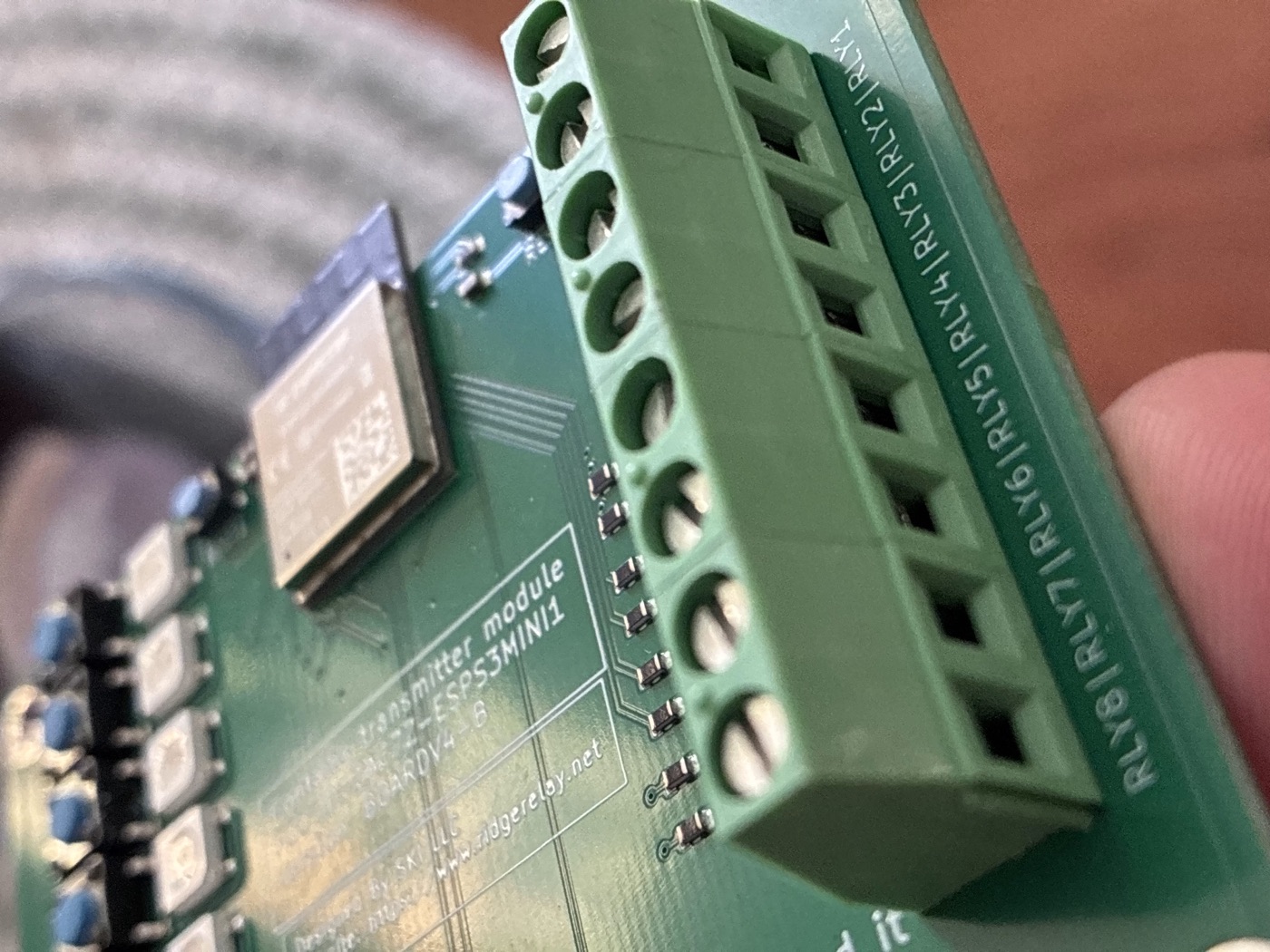
Test it
Press a board button to toggle its channel. A green LED means the board is commanding that channel on; it does not confirm that the load circuit is working.
To verify a channel, set a multimeter to continuity or resistance and connect it between GND and that channel’s RLY terminal. On: continuity, about 0 ohms. Off: open.
Pair with the app
- Hold buttons 1 and 6 until the LEDs run a blue back-and-forth sweep.
- Open the RidgeRelay app and go to pairing.
- Select the board shown as open to pairing. It appears as “SKI Relay” followed by a short ID.
- When it pairs, the LEDs stream red, yellow, then green from top to bottom.
- No Bluetooth PIN or classic pairing is needed; RidgeRelay uses BLE.
Use the app
Tap a relay tile to toggle it, rename it, choose an icon, or set your dash color. See what the app can do.